

Introduction
While my Ocean simulation is rendering in uni, it is time I started work on the second area of my project – pyro simulations. I actually had a brief experimentation with pyro before I had defined my project properly and am excited to reacquaint myself with the toolset after so many weeks. In order to learn how to create pyro simulations in Houdini I will be using another tutorial from Pluralsight: Introduction to Houdini Pyro FX by Sam Rickles. While I will only be using one tutorial for this process, it is longer than any of the individual ocean tutorials, so should bring my knowledge to a similar level. The first module in the course is an introduction to the principles of pyro simulations in Houdini.
Creating fire from the shelf
Jumping straight in, just to demonstrate how to set up a really quick pyro simulation Rickles creates a sphere and then, with the sphere network selected, hits the Flames button in the Pyro FX shelf. This immediately creates 2 new networks and modifies the sphere network as well. Immediately if you hit play you will already see we have our sphere on fire, but how did Houdini do this?
Sphere_Object1
The network created when we created our sphere was renamed after we added flames from the shelf to sphere_object1 and if you jump inside you will see a number of new nodes that were not there previously. The most important of these is the Fluid Source node (create_fuel_volume) as the name suggests it adds fuel information to the sphere geometry, preparing it to be set on fire. This is the equivalent of our “Source” networks in ocean simulation and so I will rename this network to pyro_source_sphere.
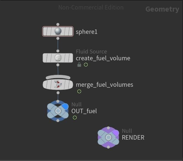
The interior of my source network.
pyro_sim
Unsurprisingly, next we have the DOP Network created by our shelf tool – pyro_sim. As before, this is where the majority of our simulation takes place and there are 3 key nodes we need to take a look at. Firstly, on the far left, is the Smoke Object (pyro). This node contains a lot of the information concerning the size and resolution of our simulation as well as options to visualise different parameters such as temperature, fuel, and divergence. Next is the Source Volume (source_fuel_from_sphere_object1) just looking at the name it should be pretty obvious what this does, it imports the fuel data from the sphere_object1 network. This data is then scaled and has its role in the simulation defined via the many parameters in this node. Lastly, the Pyro Solver is where all the calculations that define the actual look of the fire happen, from here you can control the shape, level of combustion and more or less every other detail of your fire. There is one other node in this network that is less important but still relevant, the Gas Resize Fluid Dynamic (resize_container). This essentially creates a moving bounding box for your simulation that resizes and adapts as necessary to fit the simulation, the purpose of this is to optimise your simulation times.
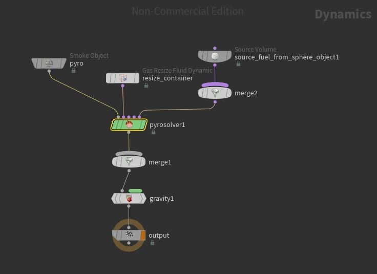
The interior of my sim network.
Pyro_Import
No surprises here if you’ve already read the ocean posts, in this network the information from the pyro_sim is grabbed and prepared to be rendered by mantra. Materials are also applied to the simulation in this network.
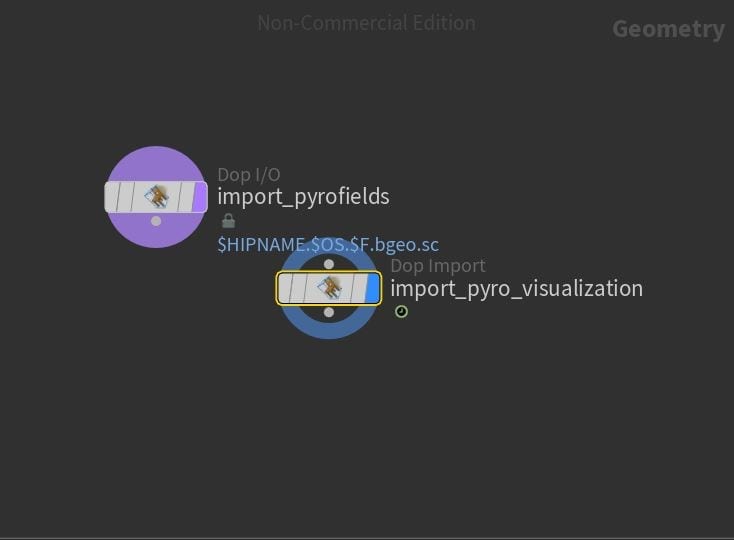
The interior of my import network.
A Closer look at the source
If you jump into the pyro_source_sphere network and display the info panel (hold MMB on the node) for the Fluid Source you will see two parameters are being created: Fuel and Temperature. Both of these are essential for pyro simulations, Fuel is the area that fire is created from and Temperature is what tells that Fuel to ignite.
Scalar Volumes
Currently both these parameters have a Scale of 1 however this can be edited in the Scalar Volumes tab, here you can increase and decrease the Scale of both parameters and the effects of this will be visible in the viewport. In addition this, in the SDF From Geometry tab, the size of our source volume relative to the original sphere geometry can be manipulated via the Edge Location and Out Feather Length values.
Rickles explains that the way interesting fire is created is not actually from the amount of fuel you have but actually through the absence of it. If you just have one solid fuel the fire will look very arbitrary and boring whereas the lack of fuel at certain points is what creates interesting flame “licks” and sparks – the best way to create this effect is by adding noise. In the Noise tab there are plenty of parameters to play with in order to get the desired size, shape and behaviour of your noise and we will look at these in greater detail in the specific simulations later.
Lastly, if you bring up the info panel again you will see the current voxel count for our Fuel and Temperature parameters (mine is 4096). The look of our final simulation will be improved by increasing this amount which can be done in the Settings tab. You will see the Division Size is already linked to the resolution of our Pyro node in the pyro_sim which is good practice to get into, however to further increase the source resolution you can add a multiplier (*0.5 for example) to add extra voxels and detail.
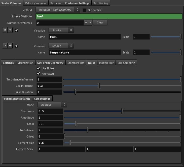
The Scalar Volumes tab.
Velocity VOlumes
Looking now at the Velocity Volumes tab we can add velocity to our source. Currently there is no Velocity as the sphere we created originally had none, however we can add Velocity by enabling the Add Velocity option. In the viewport you will see some lines that represent the direction of the velocity and by default they will be pointing vertically, the direction can be changed by manipulating the value in the Add Velocity x, y and z axis fields but to make the lines less straight (as we did with the wind in the ocean simulation) we can add Curl Noise. Enable Curl Noise in its tab and you will immediately see this linear pattern broken up. The parameters of the Curl Noise can be edited to fit the desired look and I will, again, cover them in more detail later.
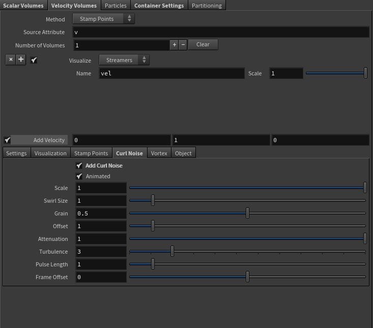
The Velocity Volumes tab.
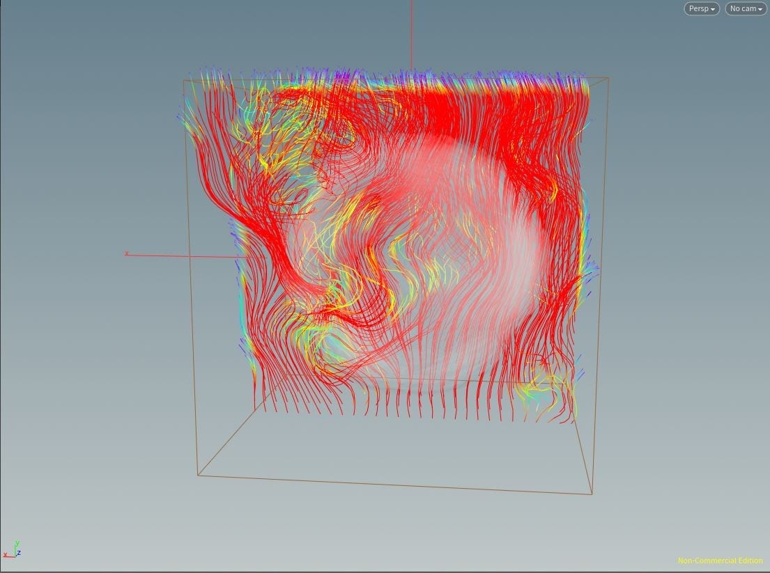
My visualised Volume and Curl Noise.
Improving the Pyro_sim
Now we’ve edited our source a bit we can look look at the DOP Network. Firstly, in the Source Volume we can see our source being imported in, from here we can further scale the parameters we are importing (in this case Volume, Temperature and Velocity) as well as change how they are brought into the simulation in the Volume Operation tab. By default these are all set to Add meaning whatever values you brought in with the source will be added to values already present in the sim but these can be changed to create different effects.
Simulation
The look of our fire is pretty unnatural at the moment so, to edit this, we will look at the Pyro Solver. Firstly in the Simulation tab, the Buoyancy Lift affects how much the Temperature will cause the flames to rise, if you take this right down then the flames will rise very slowly, increase it and they will fly upwards. Secondly, the Cooling Rate affects how quickly the temperature value of the fire is lost and therefore the speed at which the flames dissipate and become smoke, the higher the Cooling Rate the faster this effect.
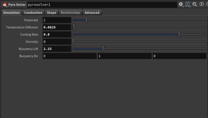
The Simulation tab.
Combustion
As I mentioned before, the Fuel parameters defines where can be ignited on a volume while the Temperature does the actual igniting. Currently in our simulation there is a lot of fire as all of our fuel is being ignited, to change this, in the Combustion tab, we can change this. The Ignition Temperature parameter defines how much Temperature has to be present for Fuel to ignite, as we increase this value less fire will be created and only areas with high levels of Temperature will burn. This effect can be further increased in the burn rate which controls how much fuel is actually burned when fire is created, lowering this value will significantly reduce the amount of flames in your sim.
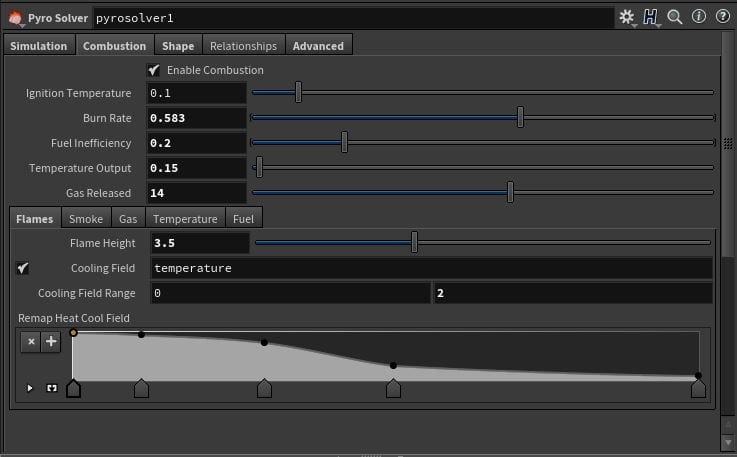
The Combustion tab.
SHAPE
In the Shape tab additional noise is added to give your fire an interesting look, Rickles recommends when troubleshooting your simulation disabling all the features to see where your problem lies. There are a whole set of parameters in here but what they do and how they are manipulated really depends on what kind of look you are going for, so I will come back to these in our specific projects later. However messing with the Shape tab can cause some issues with the bounding box which is set to only resize to fit your pyro_source_sphere network. To fix this Clamp To Maximum can be disabled in the Resize Container however this will significantly increase sim time so it is important to find a balance.
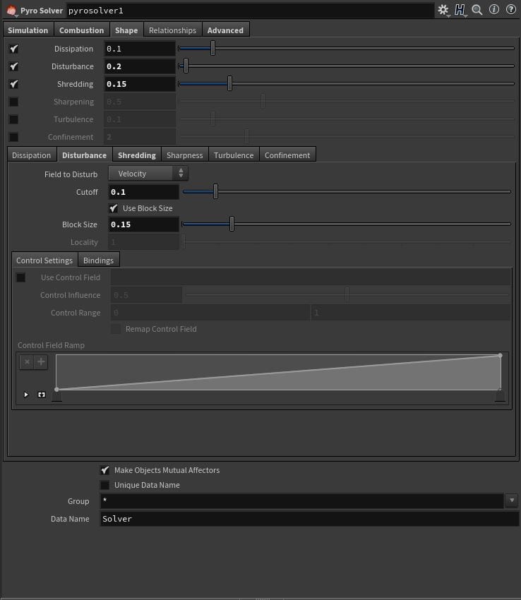
The Shape tab.
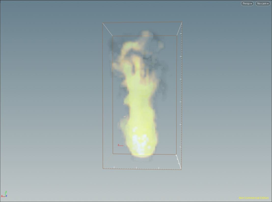
The pyro_sim visualised in the viewport.
Rendering and Exporting
To visualise what our fire will look like post-render jump into the pyro_import network and drop down a Volume Visualisation node with the DOP I/O (Import_Pyrofields) node plugged into the top. Set the Density and Diffuse Field to density as this is the attribute we want to visualise and increase the Density Scale to 5 just to better visualise what we’re doing. Now, in the Emission tab set the Emission Field to heat and the Emission scale to 1, your viewport will look very white as we haven’t yet assigned any colour values. To do this set the Emission Colour Field to temperature, set the Emission to Black Body and increase the Emission Color Ramp to 0 – 4. Now we have something that looks a bit more like fire.
Now if we hop back out and disable the pyro_source_sphere network so only the import network is being visualised then head to the render view tab and start a render, we can see what our fire will look like.
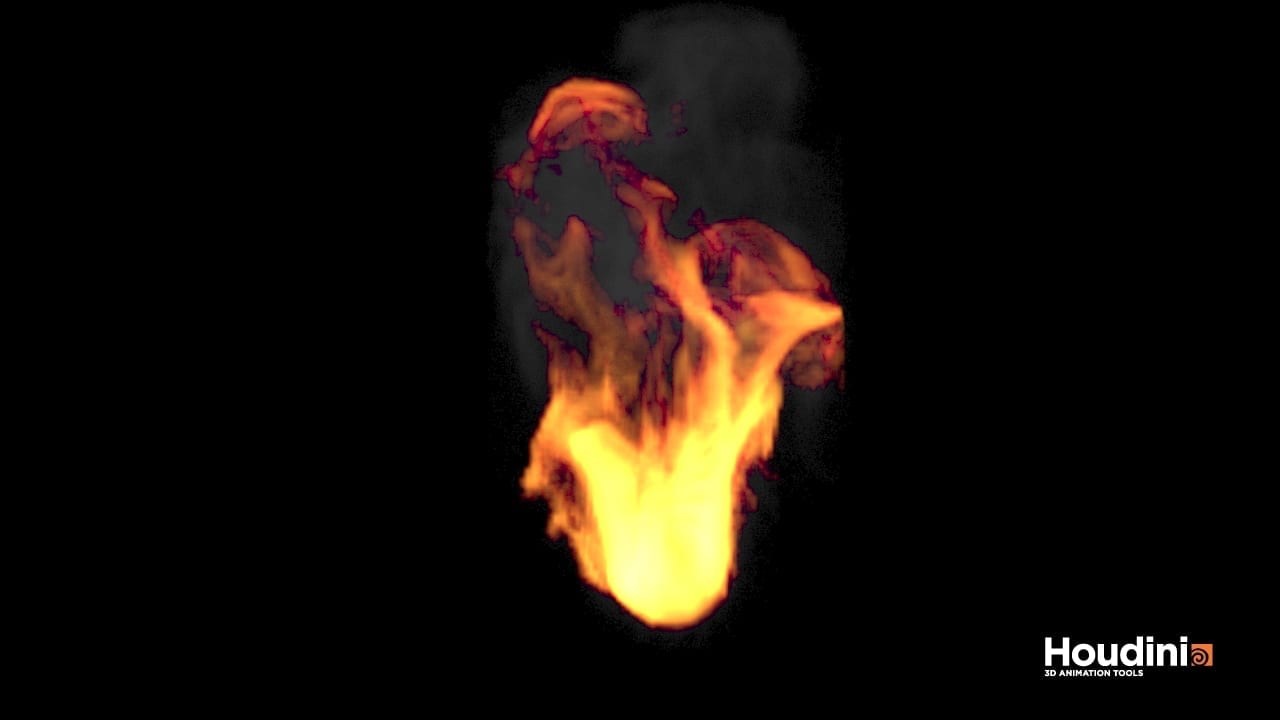
The look of the actual fire can be defined by manipulating the parameters in the Flames material and really depends on the type of look you’re going for, the render should time should not be more than few seconds so have a play with some of these values until you get the look you want, we will cover the actual purpose of each later.
REFERENCES
- Pluralsight (2016) Introduction to Houdini Pyro FX. Available from: https://app.pluralsight.com/library/courses/introduction-houdini-pyro-2504 [accessed 15th November 2018].